What Equipment Do You Need to Build a Reliable HFC Transmission Network?
Дом / Новости / Новости отрасли / What Equipment Do You Need to Build a Reliable HFC Transmission Network?
Контент
Hybrid Fibre-Coaxial (HFC) is the network architecture used by cable operators worldwide to deliver broadband internet, digital television, and voice services to residential and commercial subscribers. It combines fibre-optic cable from the headend to neighbourhood distribution nodes with coaxial cable for the final connection into homes and businesses. The performance of the entire network — bandwidth capacity, signal quality, upstream reliability, and upgrade potential — is determined by the quality and correct specification of the transmission equipment at every stage of that path. This guide covers each major equipment category in an HFC network, what technical parameters matter most, and how to evaluate options when building or upgrading a system.
The headend is the central facility from which all content and data services originate. It receives video signals from satellite and terrestrial sources, aggregates internet traffic from upstream providers, encodes and multiplexes digital content, and launches all signals onto the fibre-optic distribution network. The quality and architecture of headend equipment sets the ceiling for every downstream performance metric.
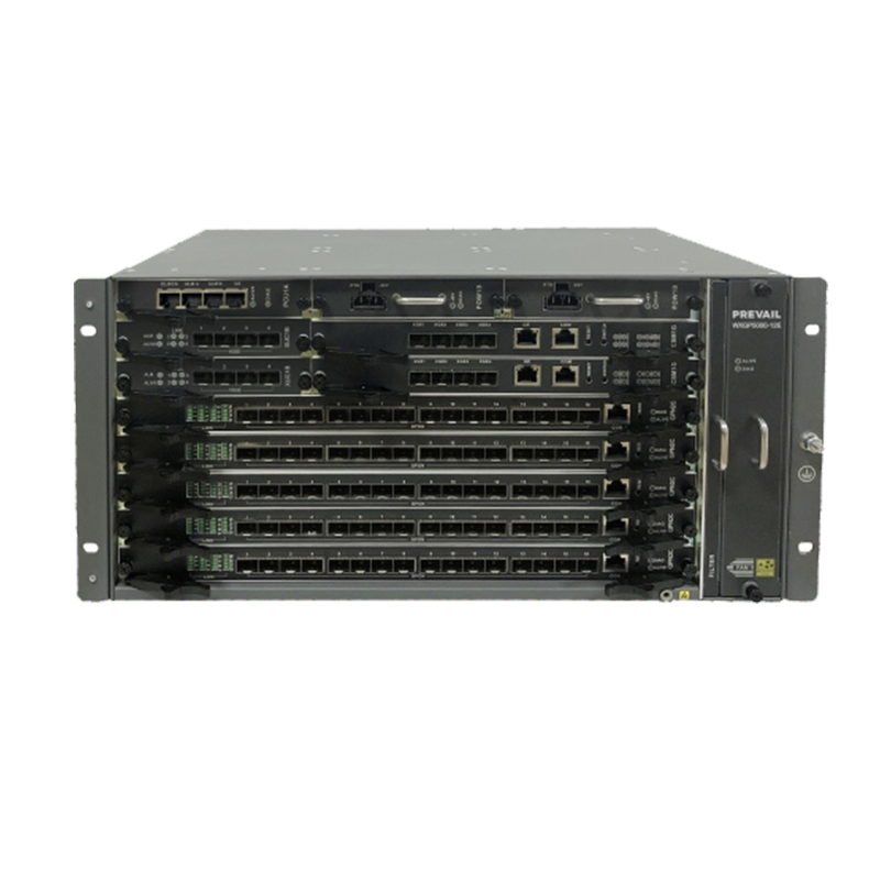
The Cable Modem Termination System (CMTS) is the headend device that manages data traffic between the operator's network and subscriber cable modems. Modern deployments use Converged Cable Access Platform (CCAP) architecture, which integrates the CMTS function with video edge QAM capabilities into a single chassis. CCAP platforms reduce headend footprint, simplify operations, and support DOCSIS 3.1 — the current standard that enables downstream speeds exceeding 10 Gbps and upstream speeds beyond 1 Gbps using OFDM and OFDMA channel bonding. When evaluating CCAP platforms, key parameters include the number of downstream and upstream ports, licensed channel capacity, support for Full Duplex DOCSIS (FDX) for future upstream expansion, and compatibility with your existing network management systems.
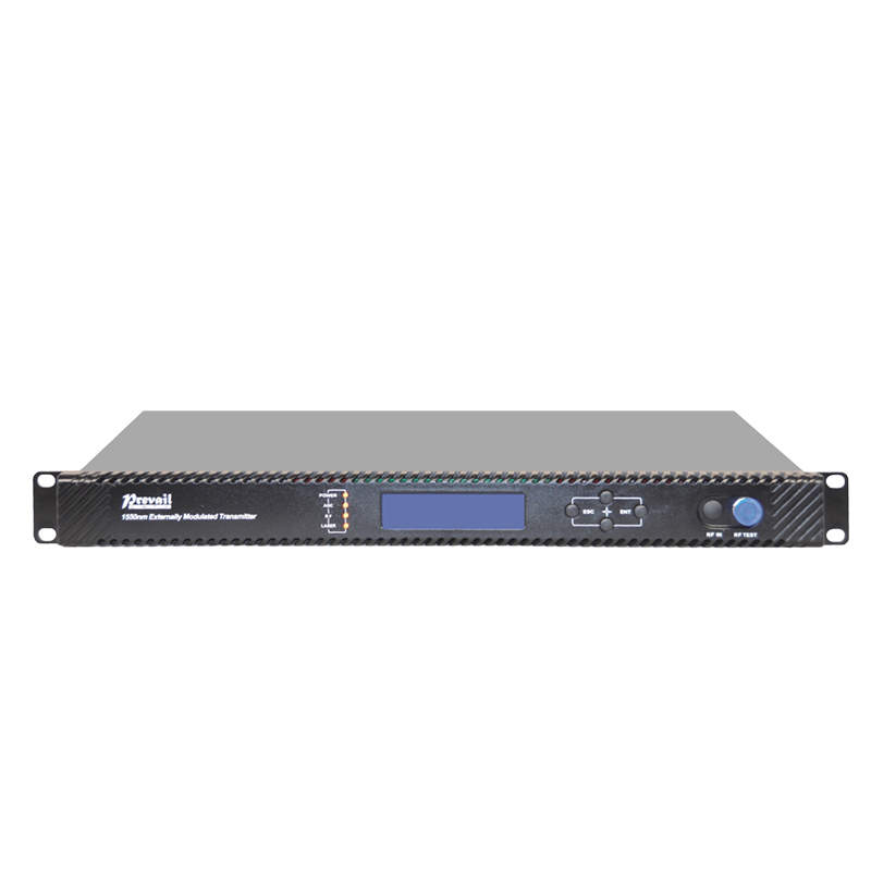
Optical transmitters convert the RF signal from the CCAP or QAM encoder into an optical signal for transmission over single-mode fibre to distribution nodes. The critical specification is optical output power and the transmitter's Composite Second Order (CSO) and Composite Triple Beat (CTB) distortion levels, which directly affect signal quality at the receiving node. DFB (Distributed Feedback) laser transmitters are the standard choice for HFC distribution, offering high output power, low noise, and excellent linearity. For longer spans or larger fibre networks, externally modulated transmitters using electro-optic modulators deliver superior performance at higher cost.
The fibre portion of an HFC network carries signals from the headend to optical nodes serving clusters of typically 125 to 500 homes passed. The design of the fibre plant — the number of nodes, the split ratio, and the fibre type — determines how much bandwidth is available per subscriber and how easily the network can be upgraded for future capacity demands.
All HFC distribution networks use single-mode fibre (SMF), which supports the low-loss, high-bandwidth transmission required over distances from a few hundred metres to tens of kilometres. ITU-T G.652D is the most widely deployed SMF standard, suitable for both analogue and digital HFC signals. Operators planning for Remote PHY or Remote MACPHY deployments — which push the digital-to-analogue conversion point from the headend out to the node — should specify low-water-peak or zero-water-peak fibre to ensure compatibility with the widest range of optical wavelengths. Fibre cable specifications to verify include attenuation per kilometre at 1310 nm and 1550 nm, chromatic dispersion, and the cable's physical protection rating for its installation environment (aerial, direct burial, or duct).
Passive optical splitters allow a single headend transmitter to feed multiple nodes, reducing headend equipment costs. The split ratio — 1:2, 1:4, 1:8 — must be balanced against the optical power budget; each split introduces approximately 3.5 dB of insertion loss, and the cumulative loss must remain within the receiver's sensitivity range. Wavelength Division Multiplexing (WDM) components allow multiple optical signals at different wavelengths to share a single fibre strand, which is essential for Remote PHY architectures where digital downstream and upstream signals must coexist with the legacy analogue RF overlay on the same fibre.
The optical node is the conversion point between the fibre and coaxial portions of the network. It receives the optical signal from the headend transmitter, converts it back to RF, and amplifies it onto the coaxial distribution cable. Node selection and placement are among the most consequential decisions in HFC network design because the node defines the serving area — and therefore the bandwidth available per subscriber group.
Key specifications to evaluate when selecting optical nodes include:
From the optical node, coaxial cable carries the RF signal through a cascade of distribution amplifiers to subscriber tap points. The length of this coaxial cascade — measured in the number of amplifiers between the node and the subscriber — is a primary determinant of signal quality and noise accumulation. Modern HFC design targets N+0 or N+1 architecture (no amplifiers or one amplifier downstream of the node) to minimise noise and maximise upstream capacity.
Trunk and distribution amplifiers compensate for the signal loss inherent in coaxial cable, which increases with both distance and frequency. Amplifier specifications that matter most include the output level (typically expressed in dBmV), noise figure (which determines how much noise the amplifier adds to the cascade), and the frequency range it supports. For networks being upgraded to extended spectrum, amplifiers must be capable of passing frequencies to 1.2 GHz or beyond. Many operators are replacing legacy 860 MHz amplifiers with wideband units during routine maintenance cycles rather than waiting for a full network rebuild, which spreads the capital expenditure and extends network life.
HFC distribution uses hardline coaxial cable with aluminium outer conductors, available in several sizes. The most common sizes and their typical applications are summarised below.
| Cable Size | Outer Diameter | Attenuation at 1 GHz | Typical Application |
| 500 series | ~19 mm | ~4.5 dB/100m | Trunk and long distribution runs |
| 412 series | ~16 mm | ~5.5 dB/100m | Distribution feeder runs |
| 350 series | ~13 mm | ~6.5 dB/100m | Short distribution and drop feeds |
| 625 series | ~25 mm | ~3.5 dB/100m | High-capacity trunk backbone |
The drop network connects the distribution cable to the subscriber premises. Drop cables are smaller-diameter, more flexible coaxial cables — typically RG-6 or RG-11 — with a foam dielectric for lower attenuation over the short distances involved. Passive components in the drop network include taps, splitters, and directional couplers, which divide the signal between multiple subscribers while maintaining acceptable signal levels at each port. Signal levels at the subscriber's cable modem must fall within the DOCSIS-specified receive power window — typically between -15 dBmV and +15 dBmV — for reliable data service. Taps are specified by their tap loss value (the signal loss to the subscriber port) and their through-loss, and selecting the right tap value for each position in the distribution cascade is essential for balancing signal levels across the serving area.
When evaluating HFC transmission equipment for a new build or upgrade, the most important principle is to specify beyond your immediate requirements. Equipment that supports extended downstream spectrum to 1.2 GHz, mid-split or high-split upstream frequencies, and Remote PHY node architecture will serve the network for a decade or more without requiring replacement. The incremental cost difference between a 862 MHz node and a 1.2 GHz node is small relative to the labour cost of returning to replace it. Similarly, CCAP platforms should be evaluated on their software upgrade path for DOCSIS 3.1 and FDX support, not just their current licensed capacity. HFC networks that are architected with upgrade headroom built in — in fibre strand count, node segmentation capability, and amplifier frequency range — consistently deliver lower total cost of ownership than those designed to the minimum specification for current demand.
WXGP5000-05E GPON OLT — это ведущее устройство OLT GPON/XG(S) PON, монтируемое на раме, которое соответствует отраслевым стандартам связи ITU-T G.984/G.987/G.988 и техническим требованиям к оборудован...
See Details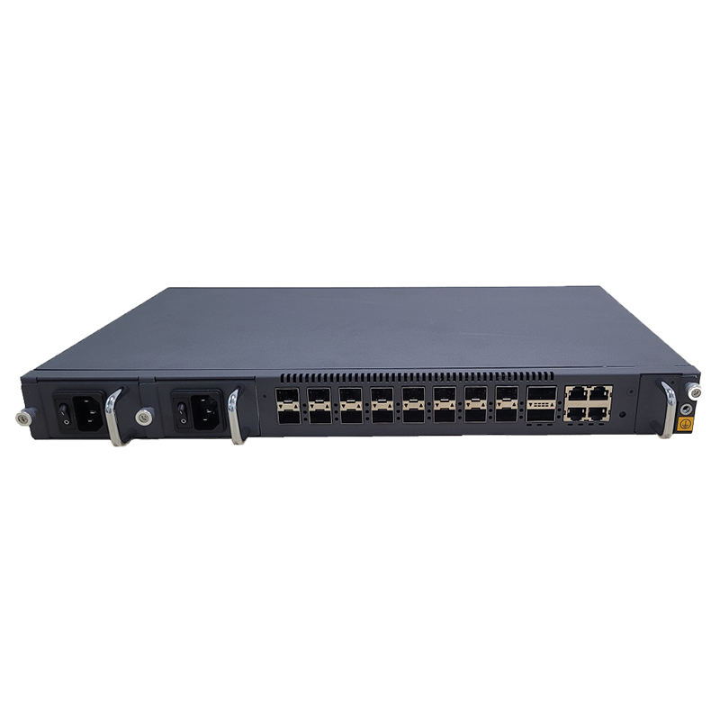
WXGP5000-08P OLT — это высокоинтегрированный XG(S)-PON OLT большой емкости для операторов, интернет-провайдеров, предприятий и кампусных приложений. Продукт соответствует техническому стандарту ITU-...
See Details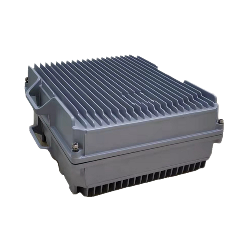
WGP5000-08FB — это наше независимо разработанное 8-портовое устройство GPON OLT для наружного применения. Он может быть оснащен встроенным оптоволоконным усилителем EDFA. Продукт соответствует техн...
See Details
WGP5000-08FP — это наше независимо разработанное 8-портовое устройство GPON OLT для наружного применения. Он может быть оснащен встроенным оптоволоконным усилителем EDFA. Продукт соответству...
See Details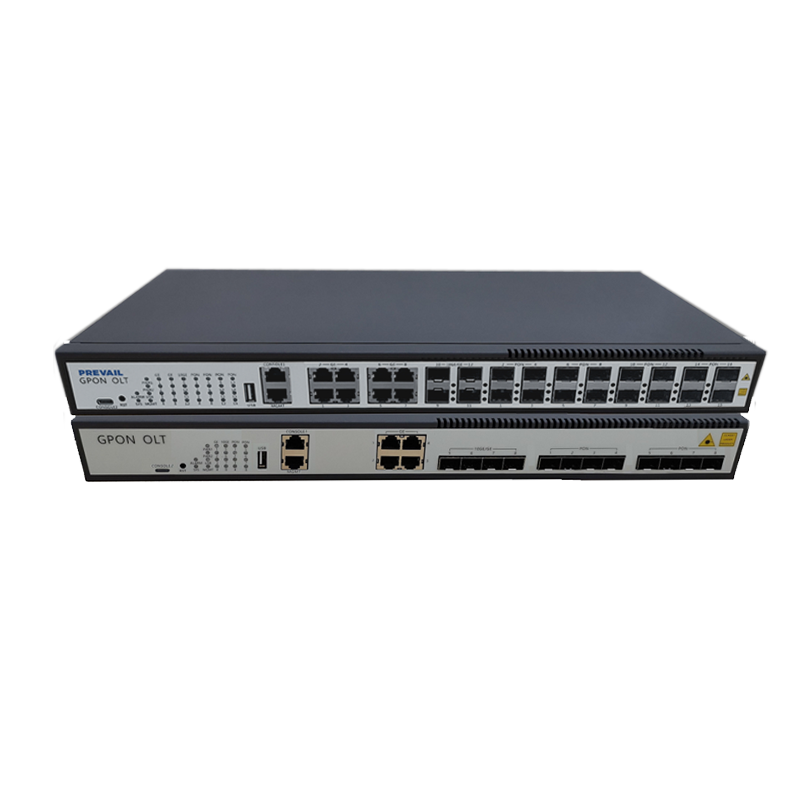
WGP5000 представляет собой высокоинтегрированный GPON OLT средней пропускной способности для операторов, интернет-провайдеров, предприятий и парковочных приложений. Продукт соответствует техниче...
See Details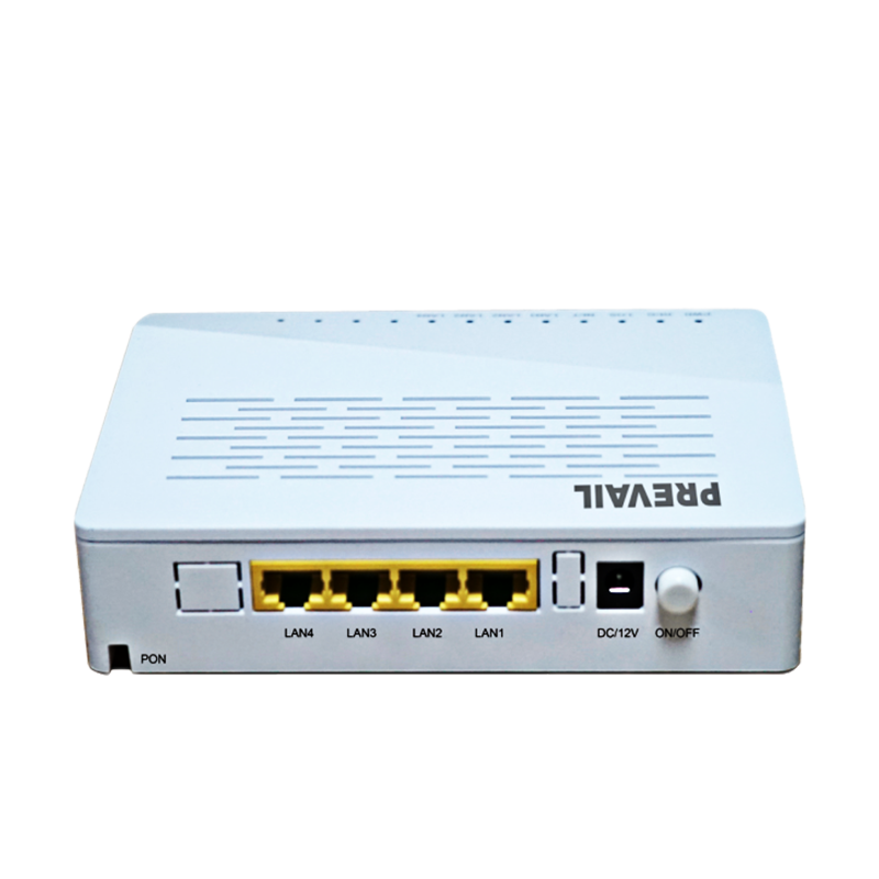
WXP4200-С Серийные терминальные продукты в основном используются для FTTH, FTTB, FTTC и других сценариев. Их можно использовать для оптоволокна для создания доступа к сети, видеомониторинга, разверт...
See Details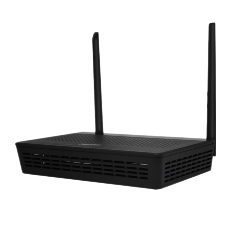
WXGP4200-W-18 представляет собой оптический сетевой блок, специально разработанный для удовлетворения высоких требований к широкополосному доступу. В основном используется в сценариях FTTH/FTTB, пре...
See Details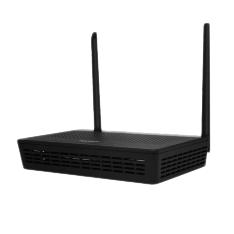
WGP3200-DW серия обеспечивает 1 оптический порт GPON, 4 адаптивных интерфейса Ethernet 10/100/1000M, 1 голосовой интерфейс и 1 интерфейс CATV, поддерживая двухдиапазонный Wi-Fi 802.11ac (2,4 ГГц и 5...
See Details
WGP3200-S-04G представляет собой оптический сетевой терминал XPON. В ONU используется схема, совместимая с EPON/GPON, с одиночным оптоволоконным входом, обеспечивающая оптический доступ 1*GEPON для ...
See Details
WXP3200-S-01 представляет собой устройство бытового шлюза с функциями маршрутизации для XPON ONU и коммутатора LAN для домашних пользователей и пользователей SOHO, соответствующее стандартам ITU-T G...
See Details
WGP3200-М Это интерфейс SFP типа ONU, компактный и изысканный, подключи и работай, с хорошим рассеиванием тепла и эффектами экранирования. Для работы его можно подключить к слотам SFP коммутаторов, ...
See Details
МЫ (Г) P3200 Устройства серии ONU могут обеспечивать 1 оптоволоконный интерфейс восходящей линии связи E(G)PON, 1 или несколько адаптивных портов GE/FE и могут иметь встроенный 1 оптический п...
See Detailstop
Э-почта:[email protected]
Телефон:+86-15967387077
Факс:+86-0571-82554407
Мобильник:+86-15967387077
QR-код включен
мобильный телефон
